Grid Fins
Ever wondered how exactly SpaceX manages to precisely land a 63.3m tall, 3.7m wide and a whooping 25600 Kg booster on a floating drone ship positioned about 650km offshore?
The intuitive answer of course is : ridiculous engineering, advanced algorithms and insane software. The on board computer ultimately adjusts the Reaction Control System (Cold Gas Thrusters) and aerodynamic control surfaces to guide the booster to the landing spot at the right velocity and orientation. However, grid fins play a very important role in this process.
Grid fins were originally developed during the Soviet Era for use on Soviet ballistic missiles made in the 70’s such as the SS-12 Scaleboard, SS-20 Saber etc.
Why are they required in the first place?
Reusable rockets like the Falcon 9 and the upcoming Starship (Super Heavy) cannot solely rely on the RCS (Reaction Control System) to adjust orientation and stabilise the vehicle during all phases of descent, where both airspeed and air density vary rapidly and sometimes dangerously. Moreover having RCS as the sole attitude control system would mean that the rocket will have to carry more of the working fluid, thus leading to a heavier booster. Therefore, an aerodynamic control surface requiring less hinge moment and that is effective at a wide range of Mach numbers (Hypersonic to Subsonic) is of great importance to such aerospace vehicles.
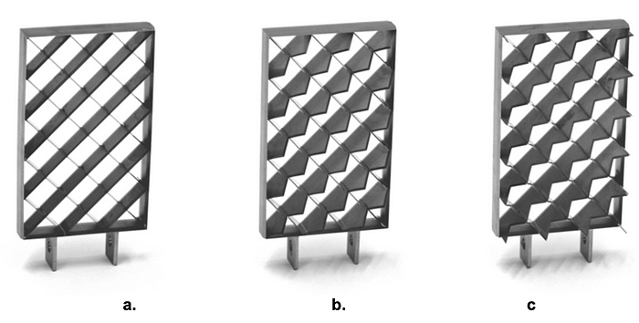
The grid fin used on the latest version of Falcon 9 (Block-5) is a locally swept peak type titanium grid fin which is unlike the earlier versions, that were planar and made out of aluminium. The current grid fins used on Falcon 9 and Falcon Heavy are the largest single piece of titanium ever manufactured (Until of course, the Super Heavy joins the fleet)

How good are they compared to planar tail fins?
Grid fins have by far been the best to satisfy the above requirements. These also known by the names of lattice wings and lattice controls, are compact unconventional aerodynamic control surfaces made up of multiple individual constituents (members) held rigidly together by a common framework. The members are conventionally high aspect ratio rectangular wings of constant chord.
Some of the major advantages they have to offer are:
1) High aerodynamic effectiveness at low weight and volume
2) Well adjustable aerodynamic characteristics for wide ranges of Mach numbers and deflection angles
3) Enhanced yaw stability at high incidence angles and improved roll stability
4) Small hinge moments with minimal shift of the center of pressure, implying that less torque and lighter machinery is required to actuate them.
5) Compact size and possibility to be folded down to the fuselage making the missile more compact and easier to store or transport.
However, there is one major drawback. The very multi-plane construction of the grid fins gives rise to relatively high level of wave drag and weak stability/effectiveness at transonic speeds due to interference of Mach cones of individual members resulting in a stronger bow shock upstream.
Can the drag problem be overcome somehow?
These effects can be mitigated by increasing the critical Mach number or by simply inducing sweep in the individual members. This change decreases the intensity of the bow shock wave and improves transonic behavior.
Wave drag reduction for a planar grid fin can be accomplished by minimizing the leading edge bluntness of individual members and total surface thickness. The members/elements can be profiled as wedge, double wedge or hexagonal airfoils. However, in some cases, these heavily scale up the manufacturing cost, which is why they are not so commonly used.
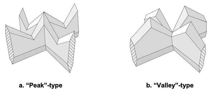
Locally swept lattice wings come mainly in two types: Peak type and Valley type


The lowest zero-lift wave drag is shown by the peak-type of the lattice wing. On the contrary, better lift to drag performance at wing incidence is shown by the valley type. The geometric parameters used to define a locally swept grid fin with a hexagonal cross section are chord c, span s, thickness t, half-angle of the leading and trailing edge sharpness, measured in the plane normal to the edges.
Where else are grid fins used?
One of the earliest noticeable applications of grid fins on launch vehicles include the Russian Soyuz Launch Escape System, a similar system is also adopted by ISRO for the upcoming Gaganyaan mission and in the Crew Escape System of the Chinese Long March 2F rocket used for the Shenzou Program.
Grid fins have featured on a variety of missiles and air to ground weapons such as the Russian Vympel NPO R-77 missile (NATO: AA-12 Adder), GBU-43(Massive Ordinance Air Blast: Most Powerful Non-Nuclear Munition), the Soviet N-1 moon rocket. Notice the range of speeds that each of the mentioned examples are designed to encounter, this shows the versatility of the lattice wing design.


What does the future hold for grid fins?
When it comes to launch vehicle technology, grids fins have become an attractive option for reusable rockets and with the improvement in computation technology and manufacturing techniques, the future looks bright for grid fins.
The Amur rocket, intended to replace the Soyuz-2, is a semi-reusable rocket is set to utilise grid fins to perform Falcon 9 style landings. The previously mentioned Super Heavy booster of SpaceX will not just make use of grid fins for attitude control but also as load bearing structures when captured by the launch tower, this is for faster turn over time and rapid re-usability. The Ariane Group plans to use grid fins on their Callisto sounding rocket and the reusable Themis rocket set to fly by 2023.


